
A run capacitor remains connected during motor operation. A start capacitor operates during the starting interval and is then disconnected by the specified switching arrangement. Some single-phase motors use both. The motor circuit, rather than the equipment name or case shape, identifies which component you need.
Why the auxiliary winding uses a capacitor
In a capacitor motor, the capacitor changes the phase of current in the auxiliary winding relative to the main winding. The winding arrangement and phase displacement help produce the rotating magnetic field needed for torque. The motor designer selects capacitance for that winding and its intended duty. Oriental Motor: why AC motors use capacitors
A permanent split capacitor, or PSC, motor keeps its run capacitor in circuit for starting and running. A capacitor-start design uses a start capacitor during acceleration. A capacitor-start, capacitor-run motor includes both functions. Those arrangements explain why a run capacitor can contribute to starting even though it is not an intermittent-duty start capacitor.
Construction follows the intended duty
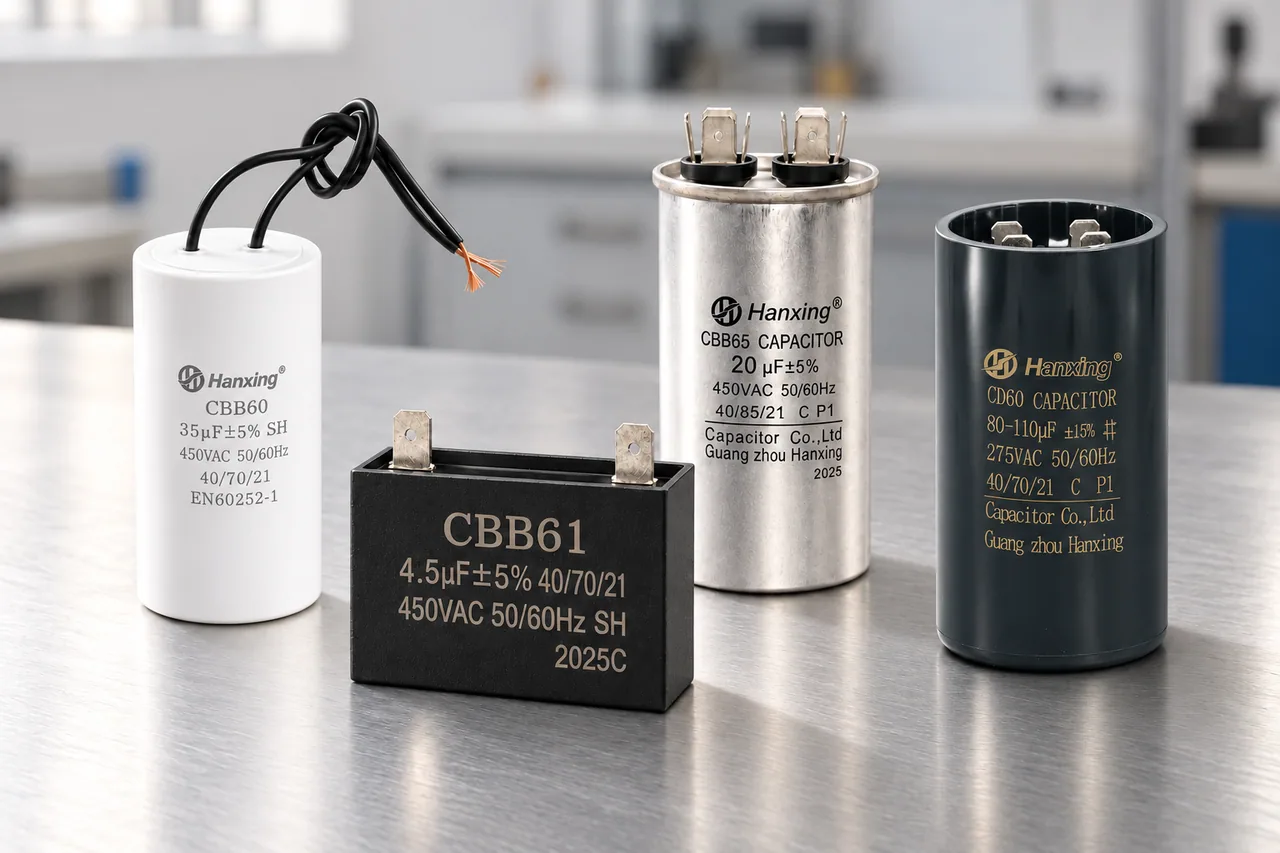
The HAN XING CBB60, CBB61 and CBB65 families are film motor run capacitors. Their insulated cylindrical, rectangular and metal-can formats suit different assemblies. CD60 uses an AC aluminium electrolytic construction for intermittent starting. Select each family for the duty specified in the motor circuit.
A start capacitor cannot replace a run capacitor for continuous operation. Likewise, a run capacitor with a convenient case cannot be assumed to meet a motor’s starting requirement. The approved replacement specification must cover construction, µF, VAC and duty together.
Ratings on a CBB65 label
The label gives 20 µF ±5%, 450 VAC and 50/60 Hz.
CD60 start-capacitor sample
CD60 start-capacitor sample marked 500 µF and 300 VAC.
Identify the circuit before buying a replacement
For a pump with a failed external capacitor, the useful starting point is the motor model and original circuit diagram. They distinguish the permanently connected part from a switched starting component. In a two-capacitor motor, label photographs for both parts prevent the run and start ratings from being mixed in the order.
If the motor hums, turns slowly or overheats, those symptoms do not prove which component failed. Supply, wiring, mechanical load and the starting switch also affect operation. A replacement decision follows diagnosis; increasing capacitance is not a substitute for it.
Identify the required motor capacitor
Send the motor diagram and original capacitor labels to identify the run or start requirement for a model proposal.