
HVAC and refrigeration capacitors
CBB65 single and dual-run capacitors for HVAC and refrigeration motors. CD60 is for separately switched starting circuits.
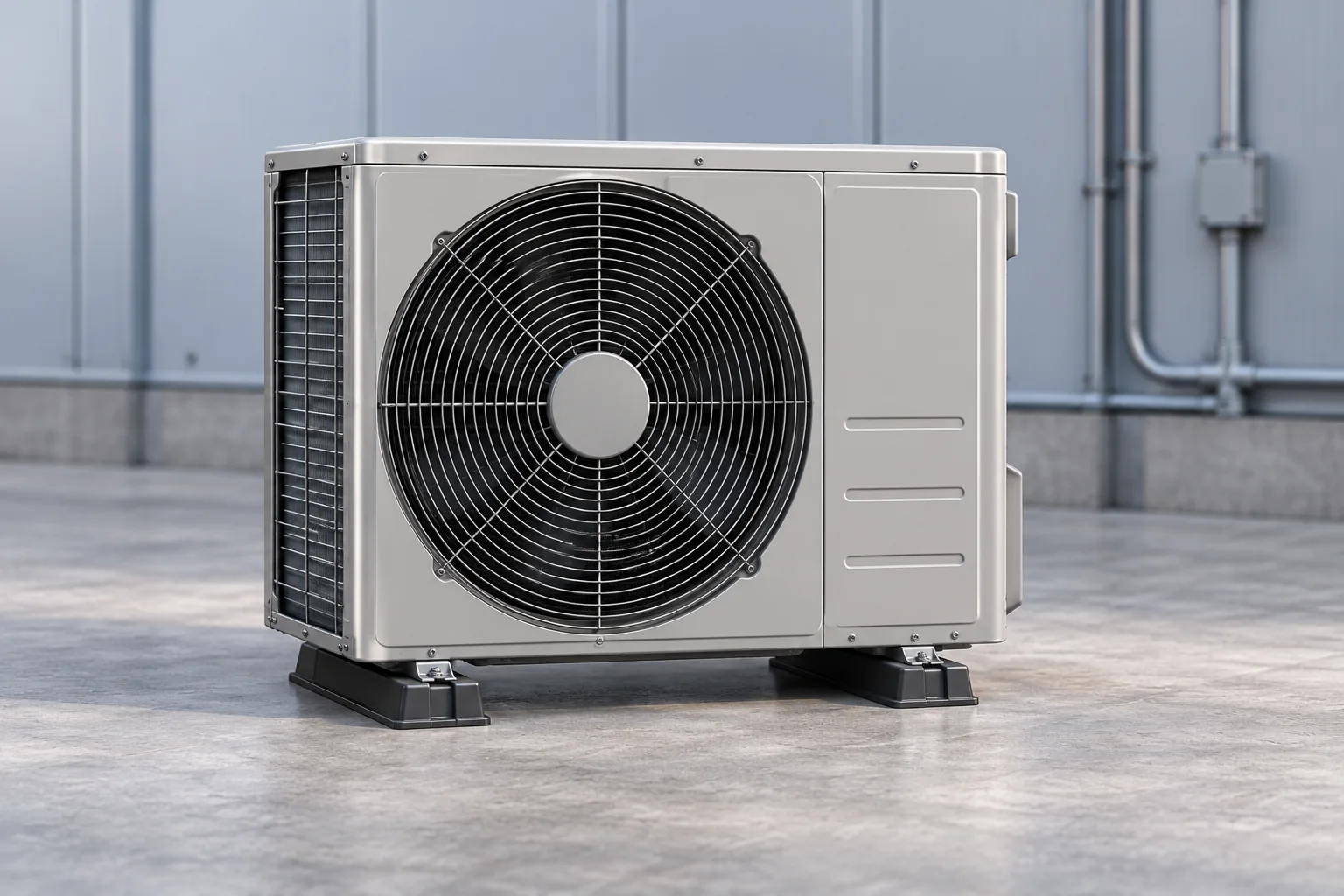
Compressor and fan capacitor circuits
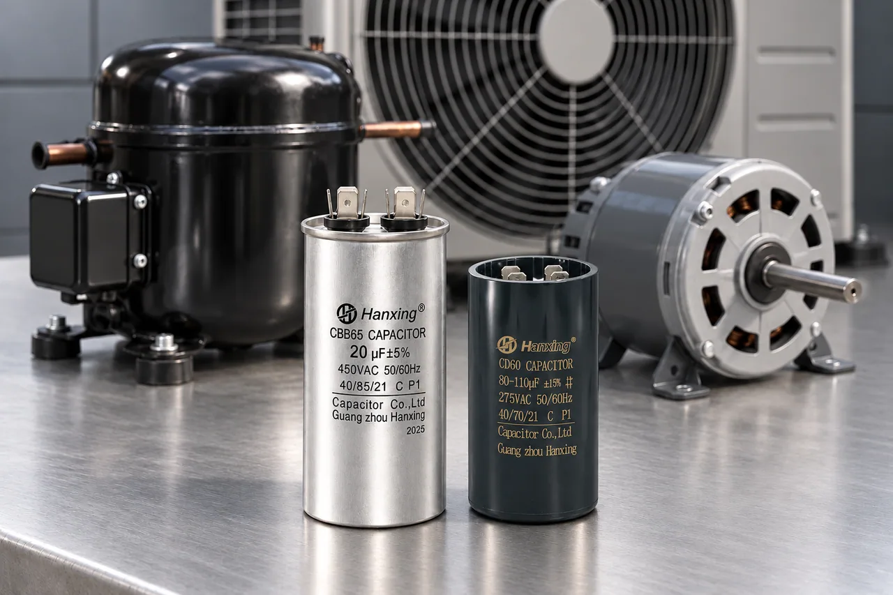
Identify each motor
List the compressor and other motors separately. Photograph each capacitor label and show where it connects on the equipment diagram.
Single or dual run
Use the original part and wiring diagram to identify the run configuration. For a dual-run part, record both µF values and which terminal group each belongs to.
Separate start circuit
CD60 is used in a separately switched starting circuit. Include its rated starting time and interval between starts.
CBB65 run and CD60 start capacitors
| Field | CBB65Run duty | CD60Start duty |
|---|---|---|
| Duty | Run; single or dual configuration. | Start; separately switched starting circuit. |
| Case / connection | Metal can; model-specific terminal groups. | Electrolytic start-capacitor case; blade terminals or wire leads. |
| Single-run µF / VAC | 2–100 µF · 110–450 VAC | Not applicable |
| Dual-run µF / VAC | 1+15 to 15+80 µF · 370–450 VAC | Not applicable |
| Start µF / VAC | Not applicable | 20–1500 µF · 110–330 VAC |
| Installation requirement | Both dual-run µF values and their assigned terminal groups. | Permitted on-time, repeat-start cycle and switching arrangement. |
| Product views | 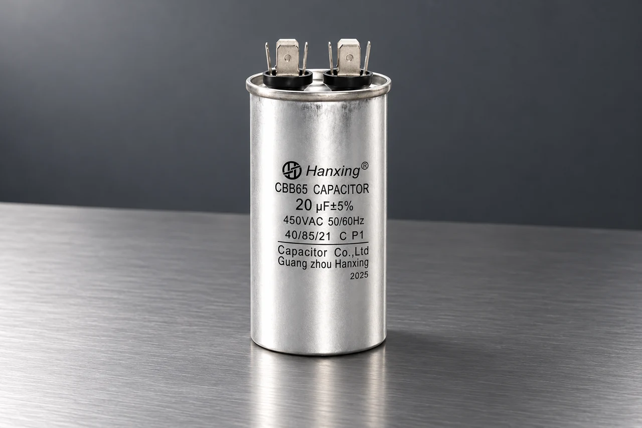 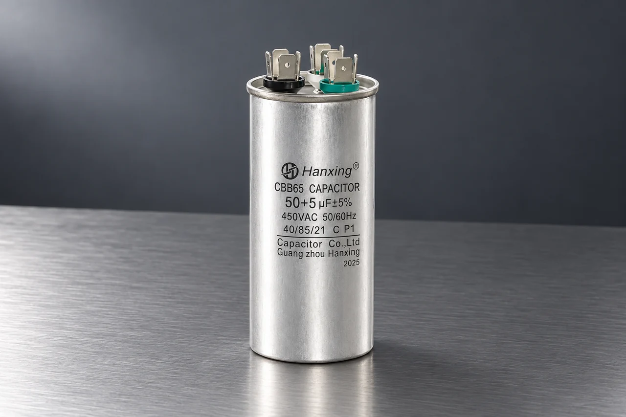 | 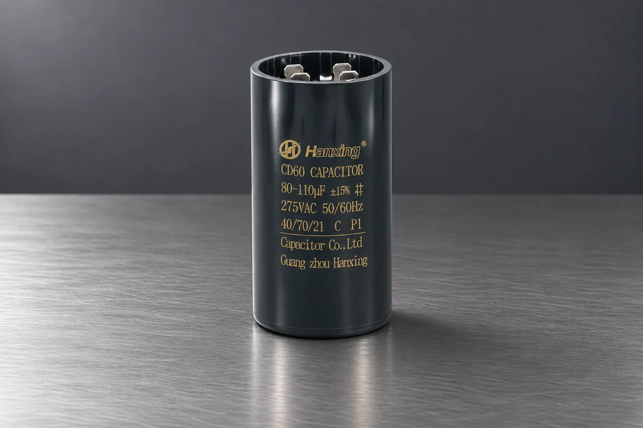 |
| Full series details | View CBB65 | View CD60 |
CBB65
- Duty
- Run; single or dual configuration.
- Case / connection
- Metal can; model-specific terminal groups.
- Single-run range
- 2–100 µF · 110–450 VAC
- Dual-run range
- 1+15 to 15+80 µF · 370–450 VAC
- Installation requirement
- Both dual-run µF values and their terminal mapping.
CD60
- Duty
- Start; separately switched starting circuit.
- Case / connection
- Electrolytic start-capacitor case; blade terminals or wire leads.
- Start range
- 20–1500 µF · 110–330 VAC
- Installation requirement
- Rated starting time, interval between starts and switching arrangement.
The model datasheet and drawing define the electrical ratings, temperature, tolerance and installed dimensions.
Other run-capacitor formats
CBB61 is another run-capacitor format used in selected air-conditioner motors. Compare its rectangular case and connections with the original part.
CBB61 applicationsTerminal mapping and installed fit
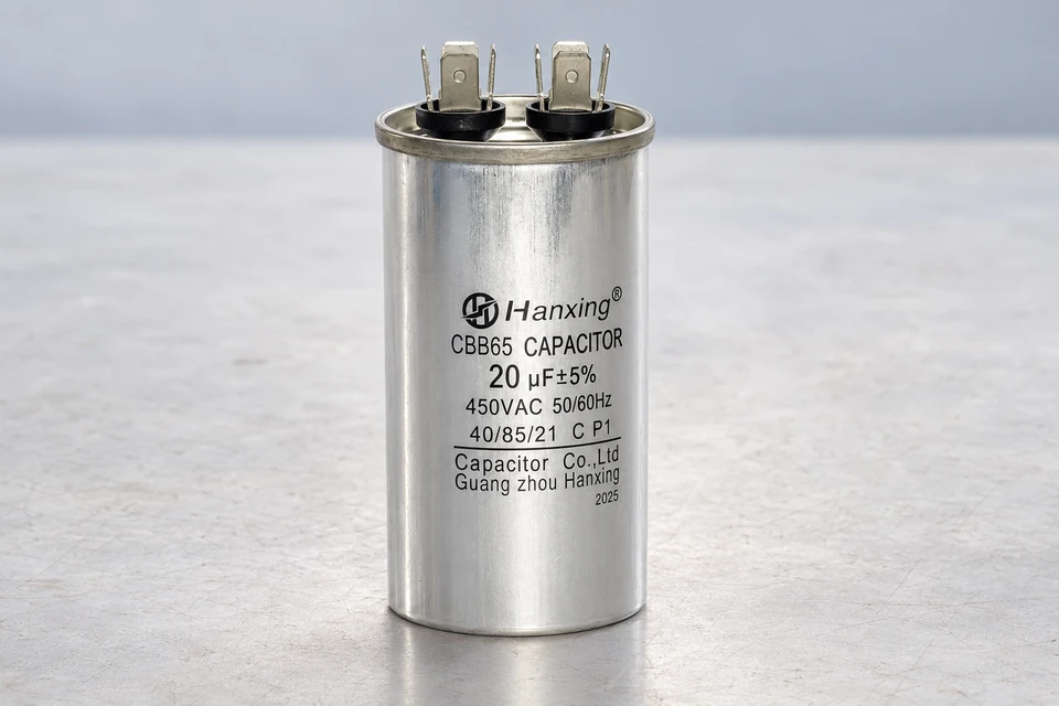
Terminal groups
Show each group marking in a terminal-end photo or drawing, then match it to the original motor diagram.
Can and mounting
Measure the can diameter and height, then check the fixing point and clearance above the terminals against the model drawing.
Starting duty
For the start capacitor, specify maximum on-time, minimum rest interval and the device that disconnects it after startup.
HVAC capacitor inquiry
Identify the compressor or motor and the capacitor required.
- Equipment and motor model, with the original capacitor label and circuit diagram.
- Drawing or measurements for the can, mounting and terminal connections.
- Quantity for each part, destination and required documents.