
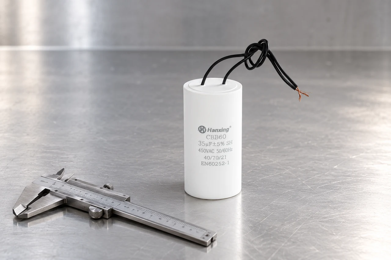
A useful drawing separates the capacitor body from the complete installed envelope. Include the fixing, terminal or lead arrangement, fitted connector and the space needed to assemble it. Two parts with the same body dimensions can require different installation space.
Measure the assembly’s limits first
Measure diameter and body height for a cylindrical part, or length, width and height for a rectangular part. Then record the maximum space available in the equipment. The drawing needs both the part dimensions and the limits of the compartment that will hold it.
Include the fixing surface and the closed cover in that envelope. A stud projects below the body; a plug projects above a terminal. If there is no room to insert a connector or tighten a nut, a nominally fitting case still cannot be assembled as intended.
Record body dimensions and connection clearances in mm. Use the approved model drawing for installation.
Terminal and lead dimensions
For blade terminals, specify width, thickness, spacing and position. Identify the mating connector and its seated height. A photograph can show the orientation, while the dimensioned drawing provides the geometry and tolerances needed for repeatable assembly.
For wire leads, state finished length and the points between which it is measured. Include exit direction, wire arrangement and termination. A mounting lug or tab needs its hole size and position; a bracket needs a usable clamping range; a stud needs thread, usable length and the required hardware.
A base stud changes the fit of a cylindrical capacitor
The supplied CBB60 photographs show lead exits and a threaded base stud. A body-height measurement excludes that stud and the routed leads. Use the proposed model drawing to define the completed arrangement rather than scaling dimensions from the photograph.
For a CBB65 metal can, include the terminal-end arrangement and bracket. Where a model uses a safety mechanism that requires movement or clearance, its installation instructions govern the space around it. A tighter bracket is not automatically a better mounting.
The stud extends beyond the case
Record the CBB60 body and base-stud dimensions separately, with the space required for leads and the fitted connector.
Leads and mounting lug
Red leads on both CBB61 samples; one case has a mounting lug. Measure the body, mounting position and full lead route against the drawing.
Use a fitted sample to approve the drawing
The drawing revision and sample reference should describe the same configuration. Fasten the capacitor in the real assembly, connect the intended harness and close the enclosure. Record any interference before approving the production configuration; preserve the approved geometry with the order.
Request a dimensioned model drawing
Include your available space, fixing method and mating connector along with the electrical rating.